Downloads
Water stills
Operating manual
I. Description of the apparatus
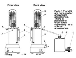
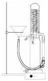
Distillation apparatus for producing of distilled water TYPE DP 4000 is identified for preparing of smaller amounts of distilled water. By way of this apparatus it is possible to prepare approximately 4 litre of distilled water at one hour. Apparatus is put together from two main parts - glass part and electrical part. Both parts are connected with plastic flange. In upper part of glass part is cooling coil. This upper part is partitioned off the lower part with glass partition. Boiling of tap water proceeds in the lower part of the glass part. Vapour comes through the tube which is connected to the centre of partition to upper part where is cooled and distilled water is drained of the distillation apparatus through the nozzle which is situated above glass partition.
II. Technical Data
|
Power consumption |
W approx. |
~3100 |
III. General instructions and safety regulations
- To avoid possible hazards pay good attention to the general instructions and safety regulations.
- When you operate with this apparatus wear protective clothing, goggles and protective gloves.
- Read and follow Operating manual carefully step by step.
- Every user must be acquainted with this Operating manual and keep it within reach at all times.
- The area in which the apparatus is to be used must conform to the appropriate electrical regulations. Connect the apparatus only to the earthen plugs and sockets.
- Set up the apparatus on solid, flat surface only.
- Use the apparatus in a dry environment only; do not use it in a potentially explosive atmosphere.
- The available voltage and type of current must correspond to the data given on the type plate.
- The electrical connection must have front end protection with fuse of at least 15 A.
- Connections to the electrical mains and water supply must be made in such way as to avoid creating dripping hazards.
- Repairs within the base of apparatus (electric circuits, heating) must be made only by authorised electricians.
- Never use force.
- Use original manufacturer’s accessories and original manufacturer’s spare parts only.
- Use hoses delivered by the manufacturer only. Do not use old hoses.
- Never send the apparatus to your supplier for repair without having cleaned it first.
Caution!
Do not operate the distillation apparatus unless it is properly connected to an earthen electrical installation which is in perfect condition. Make sure that earth connection complies with valid electrotechnic regulations. Otherwise, serious hazard of persons and fire endanger cannot be excluded.
IV. Connection to the Electrical Mains/Water Supply
|
Electrical mains: |
230 Volts, 50 Hz |
V. Picture of the apparatus
 |
|
|
Description of apparatus |
|
|
9. outlet valve |
VI. Unpacking the apparatus
- Open carton box.
- Carefully remove upper part of interior cover made from polyurethane foam an lift up the apparatus form the box.
- Check the apparatus immediately for glass breakage and other damage which may have occurred during transportation.
- When you want to bring apparatus to other place never hold it by side tube (6), hold only body of condenser and the base.
VII. Setting up the apparatus
- The apparatus set up always on a solid flat surface, have a respect to the fact that under the apparatus can temperature reach value 50°C
- The apparatus set in a dry environment.
- The lower edge of the apparatus must be level with, above edge of the sink.
- The minimum safety distance from the supply/water drain should be 1 m, to avoid the risk of splashing.
- Never set up the apparatus closer than this.
VIII. Collection of distilled water, installing of the reservoir bottle
In order to achieve conductivity of distillate water mentioned in „Technical data“, the apparatus and the reservoir bottle must form closed system. Carbon dioxide from the air dissolves in water and increases conductivity of distilled water. Recommended suitable reservoir bottle and bottle top are available as an original accessory (see XV.Ordering data for accessories). In the case when there is need not higher quality of the distilled water and the increase of the conductivity of distilled water related to dissolved carbon dioxide would not be significant, it could be possible collect distilled water simply to any suitable clear vessel in open air.
Preparing of collecting of the distilled water:
- Fit glass stopcock (1) to the hole near the bottom of the reservoir bottle (2).
- Place reservoir bottle to the right of the apparatus.
- Outlet of the stopcock must be attainable for taking of distilled water.
- Fit the tubing connection (3) to the head of the bottle.
- Fit the supplied silicone tubing to the tubing connection (3)
- Connect free end of silicone tubing to the tubing connection of the distillate drain tube (4).
IX. Protective cap
Unscrew the protective cap (5) and place it for storage on the base of the unit behind the level tube (6).
X. Connecting of the Tubing
Use the PVC tubing supplied for the connections.
Note
Dip the end of the PVC tubing into hot water (approximately 80 °C) for about 3 minutes before use. This will make the tubing flexible so that it can easily fitted on the glass tubing connection.
Connecting of the cooling water supply
- Fit the end of the tubing supplied (outer diameter 19 mm) to the bent tubing connection (7) of the still body.
- Lead the tubing to the water tap and in a case of necessity cut it off to suitable length.
- Fit the second end of the tubing to the water tap.
Connecting of the water drainage
Water from the cooler (15) is led from the cooler to the tubing (6), which is also supplier of the water to the evaporator. Surplus water is led by the bent tubing connection (8) to the sink. The water level in the evaporator is given by position of the bent tubing connection (8) on the tubing (6).
- Fit the end of the PVC tubing (outer diameter 19 mm) supplied to overflow tubing connection (8)
- The second end lead to the sink and in a case of necessity cut it off to suitable length.
- Insert the second end to the sink and safe the tube against falling out off the sink
- Don’t allow the tubing sag.
Attention:
When you are fitting the end of PVC tubing on the overflow tubing connection (8) support the level tube (6) with your hand to avoid glass breakage.
To connect the outlet valve (9)
Fit one end of PVC tubing (outer diameter 14 mm) to the outlet valve (9) cut the second end off at suitable length and insert this end to the sink and safe it against falling out.
XI. Putting into Operation
Preparing to the operation
Make sure
- Make sure that main switch (10) is in the „off“position (green lamp “mains” do not lighting).
- The screw cap (5) is unscrewed.
- Stopcock is closed
- The stopcock of the reservoir bottle and the outlet valve (9) are closed
Plug the mains supply plug into the mains socket
To adjust the water supply
- Slowly turn on water tap to allow just a small amount of water to flow through the overflow (rate of water flow approximately 0, 5 to 1 l/min).
- As soon as water in the evaporator (11) almost covers the heating spiral: press the mains switch (10). The green lamp „Mains“(12) will light up.
- As soon as the water in the evaporator starts boiling, slowly reduce the water supply at the water tap until steam starts to escape from the degassing outlet (13) at the top of still body. Do not close water tap.
- Slowly increase the water supply until it is just sufficient to stop the steam from escaping
- The water supply is thus optimally adjusted
Note:
When operating the apparatus for the first time, let it run distilling in distilling mode for one hour. Discard the distillate.
 |
|
 |
|
 |
|
XII. Interruption of water supply
If there is insufficient supplying of water or if the water flow is interrupted, steam will start escaping from the degassing outlet (13). The water level in the evaporator will drop. After approximately 5 minutes the heater will be automatically switch off.
Caution
- Close the water tap.
- Switch off the apparatus (mains switch), and allow it to cool down for at least 15 minutes.
- Clear the defect in the water supply.
- Switch off the temperature limiter : take a piece of non-conducting material (length minimal 50 and maximal outside diameter 3 mm), insert it to the hole (14) on the back side of the base of the apparatus and slightly press on it . Remove used piece of non-conducting material from the hole (14).
- To continue distilling repeat the procedure starting at XI. Putting into operation.
XIII. To switch off
- Press the main switch. The green lamp will go out.
- Close the water tap.
- Pull out mains supply plug out of the mains socket.
Caution
The water still must have cooled down completely before the water can be drained through the outlet valve (9). Close outlet valve afterwards.
XIV. Cleaning
Deposits (e.g. lime) build up during the distillation process on the interior parts of evaporator (11). This gradually reduces the quality of the distillate. When there are considerable deposits in the evaporator, or when the quality of the distillate no longer meets the requirements for the intended application, the evaporator must be cleaned. When there are heavy deposits in the cooling spiral, they must be cleaned up latter; these deposits however do not affect the quality of the distillate.
Producer cannot accept any warranty claims if the heater is damaged as a result of overheating because the apparatus has not been sufficiently cleaned.
The following items are required for cleaning:
- protective clothing, gloves and goggles
- a suitable funnel
- a funnel stand, minimal length 70 cm
- a graduated jug of minimal capacity 2 litters
- a suitable vessel for the disposal of the acetic acid
- acetic acid, 10 - 50 %
- tape water for rinsing
Warning
Disconnect apparatus from the mains by pulling plug out of the socket before cleaning. There is risk of corrosive burns. Wear protecting clothing, gloves and goggles during cleaning. Dispose of the acetic acid in accordance with approved procedures. For your personal safety we recommend disconnecting the mains supply before cleaning. Keep the reservoir bottle (2) connected. Allow the water still to cool down completely. We are recommending mark the apparatus with table for instance: “Do not switch on! Cleaning with acid”.
To clean the evaporator
- Drain the water out of the evaporator through the outlet valve (9) after the apparatus has cooled down completely
- Close the valve again
- Hang tubing of the outlet valve (9) into the vessel for the disposal of the acetic acid. For safety reasons, place the vessel in a receiving tank.
- Screw the screw cap (5) tightly onto the pressure compensation opening of the level tube.
- Insert the funnel into the free end of the tubing leading from the overflow tubing (8). If necessary, dip the end of the tubing into hot water (approximately 80°C) for about 3 minutes before fitting. Check that funnel fits tightly.
- Support the funnel in the stand. The bottom of the funnel cone must be level with the distillate drain tube (4) (see. fig. on the next page)
- Slowly pour in approximately 1 litter of acetic acid 10 - 50 %, using the graduated jug. Fill the funnel up to no more than one third of its capacity, to avoid spilling. Fill the evaporator up to no higher than the lower edge of the of the distillate drain tube (4). To regulate the filling rate: Place the funnel into a higher position to expedite the filling of the evaporator; return the funnel to a lower position to control the rate of addition of acid as it approaches the lower edge of the distillate drain tube, which point must not be exceeded.
Note
Take care that no acid drips into the reservoir bottle. If acid drip into the reservoir bottle, carefully rinse the bottle and the bottle top.
 |
To rinse the evaporator
After cleaning Let the apparatus run in distilling mode for one hour. Discard the distillate. |
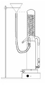
To clean the cooling spiral (15)
- After the apparatus has cooled down completely, drain the water out of the evaporator through the outlet valve (9). The outlet valve (9) must remain open.
- Hang the ends of the outlet valve (9) and the overflow tubing (8) into the vessel for disposal of the acid. For safety reasons, place the vessel in a receive tank
- Screw the screw cap (5) tightly onto the pressure compensation opening of the level tube (6).
- Disconnect the water supply tubing from the tap and insert the funnel into the free end of this tubing. Check that the funnel fits tightly.
- Support the funnel into the funnel stand (see fig. on this page). The bottom of the funnel cone must be level with the degassing outlet (13) (see fig. on this page)
- Slowly pour in approximately 300 ml of acetic acid, 10 - 50 %, using the graduated jug. Be carefully and avoid spilling.
Caution!
Acetic acid flows out outlet valve and overflow tubing into the vessel.
 |
To rinse the cooling spiral
After cleaning Let the apparatus run in distilling mode for one hour. Discard the distillate. |
XV. Return of the apparatus for the Repair
Carefully clean the instrument, and send it to your supplier. Please describe your complaint in detail.
XVI. Ordering dates for accessories
- tubing
- reservoir bottle (2 l)
- tubing connection with NS 29/32 for connection of distillate drain tube and reservoir bottle
- stand for funnel
- funnel (diameter 75 mm)
XVII. Guarantee
Producer gives 24 month guarantee for this apparatus. V guarantee expires if it would be evidenced, that attendant did not follow operating manual. Guarantee does not be applied in case of mechanical damage of apparatus as well.